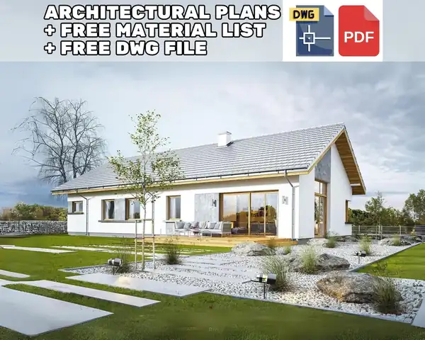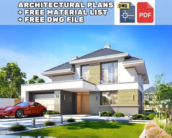
3 Bedroom 138 m2 Detailed Modern House Architectural Floor Plans 11m x 13m
- 138 m2
- 3 bed
- 2 bath
$57.20$81.72-30%View
A beginner's guide to reading floor plans: scale, dimensions, walls, doors, windows, stairs, symbols, section marks, elevations and common abbreviations.
Floor plans can look like a maze of lines, numbers and symbols the first time you open one. Once you know the conventions, though, they become the clearest way to understand a building: far more precise than a 3D render. This guide explains what you are looking at, step by step, so you can study a plan with confidence before you buy it or discuss it with a builder.
A floor plan is a horizontal slice through the building, typically about 1 to 1.5 m above the floor, seen from directly above. Everything cut by that imaginary plane, mainly walls, is drawn with heavy lines. Things below the cut, such as floor finishes, kitchen counters and furniture, are drawn with lighter lines. Things above the cut, such as upper cabinets or beams, are often shown dashed.
Each level of the house has its own floor plan. Read them together: the stair on the ground floor should line up with the stair on the upper floor.
Most drawing sheets have a title block, usually along the bottom or right edge, giving the drawing name, the scale and the sheet number. Common scales are:
A scale is only valid when the drawing is printed at the stated paper size. If you print an A3 sheet on A4, everything shrinks. That is why written dimensions are more reliable than measuring the paper with a ruler.
Dimension lines are thin lines with ticks, dots or arrows at each end and a number above. Plans usually have several layers of dimensions around the outside:
Metric plans are usually dimensioned in centimetres or millimetres; the title block or notes tell you which. Imperial plans use feet and inches, for example 12'-6" (twelve feet six inches). Room sizes are sometimes written inside each room, as width by length. Our guide to metric vs imperial plans explains how to convert.
Walls are the heaviest lines on the plan. External walls are usually thicker than internal ones because they carry insulation and cladding. Hatching or solid fill inside a wall can indicate its material or whether it is load-bearing; the legend explains the convention used on that drawing set.
Stairs are drawn as a series of parallel lines (the treads) with an arrow showing the direction of travel, often labelled UP or DN. Because the floor plan cuts through the stair partway up, there is usually a diagonal break line where the drawing stops. The number of treads and their depth determine how steep the stair is.
Kitchen worktops, sinks, hobs, toilets, basins, showers and baths are drawn with standard simplified symbols. They help you judge whether the rooms are usable, but their exact positions may change during detailed design. Check that there is enough space in front of fittings to use them comfortably.
You will often see symbols such as a circle with a letter or number and an arrow, connected by a line across the plan. These are section marks: they show where a vertical section has been cut and in which direction you are looking. The section itself appears on another sheet, labelled with the same reference, such as Section A-A.
Elevation marks work in a similar way, pointing to the views of each façade. Reading plans, sections and elevations together is how you understand heights, roof shape and levels.
A north arrow shows how the building is oriented. It matters because sunlight, views and wind all depend on direction. On a ready-made plan the arrow is only a suggestion; when the house is placed on your plot, the real orientation may differ. See how to choose a house plan for your plot.
| Abbreviation | Meaning |
|---|---|
| UP / DN | Stair direction, up or down |
| WC | Toilet |
| W/D or WM | Washer and dryer, washing machine |
| REF | Refrigerator |
| CL or WIC | Closet, walk-in closet |
| FFL | Finished floor level |
| CH | Ceiling height |
| TYP | Typical, applies to similar elements |
| EXIST | Existing |
Abbreviations vary between countries and offices, so always check the legend on the drawing set you have.
Try it on one of our plans, for example this 138 m2 three-bedroom house or a single storey 143 m2 classic house. Every plan page lists the files included; selected house plans include real-size 1:1 DWG/DXF files in centimetres, which you can open in CAD to measure any element directly. Read what's included in a house plan set for details.
Practise on a real plan Every plan page lists exactly which files are included and shows the price before you buy.
Browse house plans All plansMetric plans are commonly drawn at 1:100 or 1:50, and imperial plans at 1/4 inch or 1/8 inch to the foot. The scale is only correct when printed on the stated paper size.
Sometimes the plan shows it with a different line weight or hatch, explained in the legend, but structural drawings are the reliable source. Ask a structural engineer before removing any wall.
Dashed lines usually show items above the cutting plane, such as upper cabinets, beams, roof overhangs or a loft edge, or items hidden from view.
On the elevations, sections or a window schedule. The floor plan shows window width and position but not height.
A step-by-step checklist for matching a house plan to your land: setbacks, coverage limits, plot width, slope, orientation, access and budget.
What drawings a house plan set contains, what each sheet is for, and the practical differences between PDF, DWG and DXF files when you buy a plan online.
What decides the cost of building a 3 bedroom house: size, shape, site, foundations, region, labour, finishes and fees, and how to get a reliable estimate.